Join World's Fastest Growing B2B Network
Join World's Fastest Growing B2B Network


| MOQ | 1 set |
| Port | tianjin xingang |
| Packaging | negotiable |
| Price | Negotiable | Condition | Brand New |
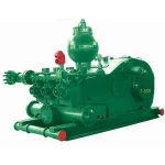
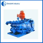
F-2200HL Mud Pump
In 2005, Baoshi Machinery successfully developed the F-2200HL mud pump, which is the first in China and has independent intellectual property rights.
Baoshi Machinery is the largest mud pump manufacturer in China and has formed the F500-2200 product series. The production and market share of mud pumps have ranked first in the world for many years. F-2200HL three-cylinder single-acting high-power, high-pressure drilling pump has a maximum power of 2200 horsepower, a maximum working pressure of 52 MPa, and a maximum displacement of 77.65 liters per second. , The drilling pump with the highest pump pressure and the largest displacement fills the gap in the research and development of high-power and high-pressure drilling pumps in China, and is listed as a new record for Chinese enterprises.
F-1600 Mud Pump (i=4,206)
F-1300, F-1600 mud pump
The F-1300 and F-1600 mud pumps designed and manufactured by our factory have the same manufacturing technical requirements and quality level as the similar FB series pumps of LTV company, and maintain the advanced structure, small size, Reliable and easy to service and maintain. In order to reduce the labor intensity of drilling workers and facilitate on-site operation, the cylinder liner is designed to be loaded from the top of the frame, and a small crane is configured on the frame for use when removing and replacing the cylinder liner. The maximum lifting capacity of the small crane is 500kg. The suction port of the F-1300 and F-1600 mud pumps is a 12" flange.
F-1300, F-1600 mud pumps use API 7# valve, and the suction valve and discharge valve can be interchanged. The cylinder material is alloy steel forging, and the three cylinders of each pump are interchangeable. The straight-through liquid cylinder is the structural design of the valve on the valve, which reduces the volume of the liquid cylinder and improves the volumetric efficiency. If the user requires, the surface of the liquid cylinder can be treated with electroless nickel plating to enhance its corrosion resistance.
|
F-1600 Performance parameters |
|
Number of strokes/min |
Rated power |
Cylinder liner diameter (mm) and rated pressure (MPa,kgf/cm2) |
||||||||||||
|
180 |
170 |
160 |
150 |
140 |
(130) |
|||||||||
|
22.7 |
232 |
25.5 |
260 |
28.8 |
294 |
32.7 |
334 |
34.3 |
350 |
34.3 |
350 |
|||
|
KW |
HP |
Displacement(L/S) |
||||||||||||
|
130 |
1275 |
1733 |
50.42 |
50.42 |
44.97 |
44.97 |
39.83 |
39.83 |
35.01 |
35.01 |
30.50 |
30.50 |
26.30 |
26.30 |
|
120※ |
1176 |
1600 |
46.54 |
46.54 |
41.51 |
41.51 |
36.77 |
36.77 |
32.32 |
32.32 |
28.15 |
28.15 |
24.27 |
24.27 |
|
110 |
1078 |
1467 |
54.66 |
54.66 |
38.05 |
38.05 |
33.71 |
33.71 |
29.62 |
29.62 |
25.81 |
25.81 |
22.25 |
22.25 |
|
100 |
980 |
1333 |
38.78 |
38.78 |
34.59 |
34.59 |
30.64 |
30.64 |
26.93 |
26.93 |
23.46 |
23.46 |
20.23 |
20.23 |
|
90 |
882 |
1200 |
34.90 |
34.90 |
31.13 |
31.13 |
27.58 |
27.58 |
24.24 |
24.24 |
21.11 |
21.11 |
18.21 |
18.21 |
|
1 |
0.3878 |
0.3878 |
0.3459 |
0.3459 |
0.3064 |
0.3064 |
0.2693 |
0.2693 |
0.2346 |
0.2346 |
0.2023 |
0.2023 |
||
Note: 1. Calculated based on 100% volumetric efficiency and 90% mechanical efficiency.
2. ※Recommended number of strokes and input power during continuous operation.
|
F-1300 Performance parameters( i=4.206) |
|
Number of strokes/min |
Rated power |
Cylinder liner diameter (mm) and rated pressure (MPa,kgf/cm2) |
||||||||||||
|
180 |
170 |
160 |
150 |
140 |
(130) |
|||||||||
|
18.5 |
189 |
20.7 |
211 |
23.4 |
239 |
26.6 |
272 |
30.5 |
312 |
34.3 |
350 |
|||
|
KW |
HP |
Displacement(L/S) |
||||||||||||
|
130 |
1036 |
1408 |
50.42 |
50.42 |
44.97 |
44.97 |
39.83 |
39.83 |
35.01 |
35.01 |
30.50 |
30.50 |
26.30 |
26.30 |
|
120※ |
956 |
1300 |
46.54 |
46.54 |
41.51 |
41.51 |
36.77 |
36.77 |
32.32 |
32.32 |
28.15 |
28.15 |
24.27 |
24.27 |
|
110 |
876 |
1192 |
54.66 |
54.66 |
38.05 |
38.05 |
33.71 |
33.71 |
29.62 |
29.62 |
25.81 |
25.81 |
22.25 |
22.25 |
|
100 |
797 |
1083 |
38.78 |
38.78 |
34.59 |
34.59 |
30.64 |
30.64 |
26.93 |
26.93 |
23.46 |
23.46 |
20.23 |
20.23 |
|
90 |
717 |
975 |
34.90 |
34.90 |
31.13 |
31.13 |
27.58 |
27.58 |
24.24 |
24.24 |
21.11 |
21.11 |
18.21 |
18.21 |
|
1 |
0.3878 |
0.3878 |
0.3459 |
0.3459 |
0.3064 |
0.3064 |
0.2693 |
0.2693 |
0.2346 |
0.2346 |
0.2023 |
0.2023 |
||
Note: 1. Calculated based on 100% volumetric efficiency and 90% mechanical efficiency.
2. ※Recommended number of strokes and input power during continuous operation.
F-1000 Mud Pump (i=4..207)
F-500, F-800, F-1000 mud pump
(1) Power end (frame, pinion shaft, crankshaft, crosshead, intermediate tie rod)
1. Features of power end, herringbone gear transmission without undercut.
Alloy steel integral crankshaft. Replaceable crosshead guides. The frame adopts steel welded parts, which has high strength, good rigidity and light weight. The middle tie rod packing adopts double-layer sealing structure, and the sealing effect is good. The power end adopts a combination of forced lubrication and splash lubrication.
2. Rack
The frame is welded by steel plates, and after stress relief treatment, it has good rigidity and high strength. The crankshaft bearing adopts a rib plate reinforced structure. The necessary oil pool and oil circuit system are set in the frame for cooling and lubrication.
3. Crankshaft
The crankshaft is an alloy steel casting. The crankshaft is equipped with a large ring gear, connecting rods, bearings, etc. The tooth shape of the large ring gear is herringbone teeth, and the inner hole of the large ring gear is an interference fit with the crankshaft, and is fastened with bolts and lock nuts. The big end of the connecting rod is respectively installed on the three eccentric turns of the crankshaft through single row short cylindrical roller bearings, and the small end is installed on the cross tip pin through double row long cylindrical roller bearings. Both ends of the crankshaft are double row radial spherical roller bearings.
4. Pinion shaft
The pinion shaft is an alloy steel forging, a herringbone gear is processed on the shaft, and a medium-hard tooth surface is used. In order to facilitate maintenance, a single-row radial long cylindrical roller bearing with no ribs on the inner ring is selected. Both ends of the shaft are extended, and a pulley or sprocket can be installed at either end.
5. Cross head and middle tie rod
The material of the cross head and the cross head guide plate is inoculated cast iron of American ASTM A48-83, which has good wear resistance and long service life. F-800, F-1000 mud pump adopts upper and lower guide plate structure, and the concentricity can be adjusted by adding gaskets at the lower guide plate. The F-500 pump adopts a guide cylinder structure. The flange bolt connection between the cross head and the intermediate tie rod is a pin hole fit. This rigid connection method ensures the concentricity between the intermediate tie rod and the crosshead. The middle tie rod and the piston rod are connected by a clamp, and the light weight clamp makes the connection between the middle tie rod and the piston rod convenient and reliable.
(2) Hydraulic end (liquid cylinder, valve assembly, cylinder liner, piston)
1. Liquid cylinder
The material of the liquid cylinder is alloy steel forgings, and the three liquid cylinders of each pump are interchangeable. The straight-through liquid cylinder is the structural design of the valve on the valve, which reduces the volume of the liquid cylinder and improves the volumetric efficiency. If the user requires, the surface of the liquid cylinder can be treated with electroless nickel plating to enhance its corrosion resistance. The discharge port is equipped with a discharge air bag, a shear pin safety valve and a discharge filter screen. The suction port of F-500 mud pump is 8" flange, the suction port of F-800 mud pump is 10" flange, and the suction port of F-1000 mud pump is 12" flange.
2. Valve assembly
The suction valve and discharge valve of the above three types of pumps can be interchanged. The F-500 pump uses the API 5# valve, and the F-800 and F-1000 mud pumps use the API 6# valve.
3. Cylinder liner
Bimetallic cylinder liner can be used, the inner lining of the cylinder liner is made of wear-resistant cast iron, the hardness is up to HRC60-65, the cylinder liner is wear-resistant and corrosion-resistant, and the surface finish of the inner hole is high. The cylinder liner is loaded into the cylinder head hole at the front of the hydraulic cylinder. After the cylinder sleeve is completed, it is fixed with a cylinder jack, a cylinder head plug and a cylinder head.
4. Piston and piston rod
It is sealed by a cylindrical surface and a rubber sealing ring, and is pressed with a locking nut with anti-loosening. After tightening the nut, it can not only prevent the piston from loosening, but also play a sealing role. The hydraulic cylinders, cylinder liners, pistons, valve bodies, valve seats, valve springs, seals, valve covers, cylinder heads and other components of the hydraulic end of the F-800 and F-1000 mud pumps can be interchanged.
(3) Spray system
It is composed of spray pump, cooling water tank, spray pipe, etc. Its function is to perform necessary cooling and flushing of cylinder liner and piston to improve the service life of cylinder liner and piston. The spray pump is a centrifugal pump, which can be driven by a pulley on the shaft extension of the input shaft, or it can be driven by a motor alone, and water is used as a cooling lubricant. The nozzle is installed on the clamp connecting the intermediate tie rod and the piston rod, and can reciprocate with the piston. The nozzle is very close to the end face of the piston, so that the lubricating coolant can always flush the contact surface between the piston and the cylinder liner. Fixed sprinkler pipes can also be used, which have the characteristics of durable sprinkler pipes.
(4) Lubrication system
The power end adopts a combination of forced lubrication and splash lubrication. The gear oil pump installed in the oil tank sends the pressure oil to the crosshead, the intermediate tie rod, the crosshead guide plate and the bearings respectively through the lubrication line, so as to achieve forced lubrication. For the purpose, the working condition of the gear oil pump can be observed through the pressure gauge at the rear of the frame.
(5) Perfusion system
In order to avoid air locks when the pump inlet pressure is low, each mud pump can be equipped with an irrigation system. The perfusion system consists of the perfusion pump and its base, butterfly valve and corresponding manifold. The perfusion pump is driven by a special electric motor and is mounted on the suction manifold of the pump. The priming pump can also be belt-driven by the mud pump input shaft to reduce the supply of the rig's total power generation.
F-1000 performance parameters
|
Number of strokes/min |
Rated power |
Cylinder liner diameter (mm) and rated pressure (MPa,kgf/cm2) |
||||||||||||||
|
170 |
160 |
150 |
140 |
130 |
120 |
110 |
||||||||||
|
16.4 |
167 |
18.5 |
189 |
21.1 |
215 |
24.2 |
247 |
28.0 |
286 |
32.9 |
336 |
34.3 |
350 |
|||
|
KW |
HP |
Displacement(L/S) |
||||||||||||||
|
150 |
788 |
1072 |
43.24 |
43.24 |
38.30 |
38.30 |
33.66 |
33.66 |
29.33 |
29.33 |
25.29 |
25.29 |
21.55 |
21.55 |
18.10 |
18.10 |
|
140※ |
735 |
1000 |
40.36 |
40.36 |
35.75 |
35.75 |
31.42 |
31.42 |
27.37 |
27.37 |
23.60 |
23.60 |
20.11 |
20.11 |
16.90 |
16.90 |
|
130 |
683 |
929 |
37.47 |
37.47 |
33.20 |
33.20 |
29.18 |
29.18 |
25.43 |
25.43 |
21.91 |
21.91 |
18.67 |
18.67 |
15.69 |
15.69 |
|
120 |
630 |
857 |
34.59 |
34.59 |
30.64 |
30.64 |
26.93 |
26.93 |
23.46 |
23.46 |
20.23 |
20.23 |
17.24 |
17.24 |
14.48 |
14.48 |
|
110 |
578 |
786 |
31.71 |
31.71 |
28.09 |
28.09 |
24.69 |
24.6 |
21.51 |
21.51 |
18.54 |
18.54 |
15.80 |
15.80 |
13.28 |
13.28 |
|
100 |
525 |
714 |
28.83 |
28.83 |
25.53 |
25.53 |
22.44 |
22.44 |
19.55 |
19.55 |
16.86 |
16.86 |
14.36 |
14.36 |
12.07 |
12.07 |
|
1 |
0.2883 |
0.2883 |
0.2553 |
0.2553 |
0.2244 |
0.2244 |
0.1955 |
0.1955 |
0.1686 |
0.1686 |
0.1436 |
0.1436 |
0.1207 |
0.1207 |
||
Note: 1. Calculated based on 100% volumetric efficiency and 90% mechanical efficiency.
2. ※Recommended number of strokes and input power during continuous operation.
F-800 Mud Pump (i=4.185)
F-500, F-800, F-1000 mud pump
(1) Power end (frame, pinion shaft, crankshaft, crosshead, intermediate tie rod)
1. Features of the power end
No undercut herringbone gear drive.
Alloy steel integral crankshaft. Replaceable crosshead guides. The frame adopts steel welded parts, which has high strength, good rigidity and light weight.
The middle tie rod packing adopts double-layer sealing structure, and the sealing effect is good. The power end adopts a combination of forced lubrication and splash lubrication.
2. Rack
The frame is welded by steel plates, and after stress relief treatment, it has good rigidity and high strength. The crankshaft bearing adopts a rib plate reinforced structure. The necessary oil pool and oil circuit system are set in the frame for cooling and lubrication.
3. Crankshaft
The crankshaft is an alloy steel casting. The crankshaft is equipped with a large ring gear, connecting rods, bearings, etc. The tooth shape of the large ring gear is herringbone teeth, and the inner hole of the large ring gear is an interference fit with the crankshaft, and is fastened with bolts and lock nuts. The big end of the connecting rod is respectively installed on the three eccentric turns of the crankshaft through single row short cylindrical roller bearings, and the small end is installed on the cross tip pin through double row long cylindrical roller bearings. Both ends of the crankshaft are double row radial spherical roller bearings.
4. Pinion shaft
The pinion shaft is an alloy steel forging, a herringbone gear is processed on the shaft, and a medium-hard tooth surface is used. In order to facilitate maintenance, a single-row radial long cylindrical roller bearing with no ribs on the inner ring is selected. Both ends of the shaft are extended, and a pulley or sprocket can be installed at either end.
5. Cross head and middle tie rod
The material of the cross head and the cross head guide plate is inoculated cast iron of American ASTM A48-83, which has good wear resistance and long service life. F-800, F-1000 mud pump adopts upper and lower guide plate structure, and the concentricity can be adjusted by adding gaskets at the lower guide plate. The F-500 pump adopts a guide cylinder structure. The flange bolt connection between the cross head and the intermediate tie rod is a pin hole fit. This rigid connection method ensures the concentricity between the intermediate tie rod and the crosshead. The middle tie rod and the piston rod are connected by a clamp, and the light weight clamp makes the connection between the middle tie rod and the piston rod convenient and reliable.
(2) Hydraulic end (liquid cylinder, valve assembly, cylinder liner, piston)
1. Liquid cylinder
The material of the liquid cylinder is alloy steel forgings, and the three liquid cylinders of each pump are interchangeable. The straight-through liquid cylinder is the structural design of the valve on the valve, which reduces the volume of the liquid cylinder and improves the volumetric efficiency. If the user requires, the surface of the liquid cylinder can be treated with electroless nickel plating to enhance its corrosion resistance.
The discharge port is equipped with a discharge air bag, a shear pin safety valve and a discharge filter screen. The suction port of F-500 mud pump is 8" flange, the suction port of F-800 mud pump is 10" flange, and the suction port of F-1000 mud pump is 12" flange.
2. Valve assembly
The suction valve and discharge valve of the above three types of pumps can be interchanged. The F-500 pump uses the API 5# valve, and the F-800 and F-1000 mud pumps use the API 6# valve.
3. Cylinder liner
Bimetallic cylinder liner can be used, the inner lining of the cylinder liner is made of wear-resistant cast iron, the hardness is up to HRC60-65, the cylinder liner is wear-resistant and corrosion-resistant, and the surface finish of the inner hole is high. The cylinder liner is loaded into the cylinder head hole at the front of the hydraulic cylinder. After the cylinder sleeve is completed, it is fixed with a cylinder jack, a cylinder head plug and a cylinder head.
4. Piston and piston rod
It is sealed by a cylindrical surface and a rubber sealing ring, and is pressed with a locking nut with anti-loosening. After tightening the nut, it can not only prevent the piston from loosening, but also play a sealing role.
The hydraulic cylinders, cylinder liners, pistons, valve bodies, valve seats, valve springs, seals, valve covers, cylinder heads and other components of the hydraulic end of the F-800 and F-1000 mud pumps can be interchanged.
(3) Spray system
It is composed of spray pump, cooling water tank, spray pipe, etc. Its function is to perform necessary cooling and flushing of cylinder liner and piston to improve the service life of cylinder liner and piston. The spray pump is a centrifugal pump, which can be driven by a pulley on the shaft extension of the input shaft, or it can be driven by a motor alone, and water is used as a cooling lubricant.
The nozzle is installed on the clamp connecting the intermediate tie rod and the piston rod, and can reciprocate with the piston. The nozzle is very close to the end face of the piston, so that the lubricating coolant can always flush the contact surface between the piston and the cylinder liner. Fixed sprinkler pipes can also be used, which have the characteristics of durable sprinkler pipes.
(4) Lubrication system
The power end adopts a combination of forced lubrication and splash lubrication. The gear oil pump installed in the oil tank sends the pressure oil to the crosshead, the intermediate tie rod, the crosshead guide plate and the bearings respectively through the lubrication line, so as to achieve forced lubrication. For the purpose, the working condition of the gear oil pump can be observed through the pressure gauge at the rear of the frame.
(5) Perfusion system
In order to avoid air locks when the pump inlet pressure is low, each mud pump can be equipped with an irrigation system. The perfusion system consists of the perfusion pump and its base, butterfly valve and corresponding manifold. The perfusion pump is driven by a special electric motor and is mounted on the suction manifold of the pump. The priming pump can also be belt-driven by the mud pump input shaft to reduce the supply of the rig's total power generation.
|
F-800 performance parameters |
|
Number of strokes/min |
Rated power |
Cylinder liner diameter (mm) and rated pressure (MPa,kgf/cm2) |
||||||||||||||||
|
170 |
160 |
150 |
140 |
130 |
120 |
110 |
100 |
|||||||||||
|
13.6 |
139 |
15.4 |
157 |
17.5 |
178 |
20.1 |
205 |
23.3 |
237 |
27.3 |
278 |
32.5 |
331 |
34.3 |
350 |
|||
|
KW |
HP |
Displacement(L/S) |
||||||||||||||||
|
160 |
627 |
853 |
41.51 |
41.51 |
36.77 |
36.77 |
32.32 |
32.32 |
28.15 |
28.15 |
24.27 |
24.27 |
20.68 |
20.68 |
17.38 |
17.38 |
14.36 |
14.36 |
|
150※ |
588 |
800 |
38.92 |
38.92 |
34.47 |
34.47 |
30.30 |
30.30 |
26.39 |
26.39 |
22.96 |
22.96 |
19.39 |
20.68 |
16.29 |
16.29 |
13.47 |
13.47 |
|
140 |
549 |
747 |
36.32 |
36.32 |
32.17 |
32.17 |
28.28 |
28.28 |
24.63 |
24.63 |
21.24 |
21.24 |
18.10 |
18.10 |
15.21 |
15.21 |
12.57 |
12.57 |
|
130 |
510 |
693 |
33.73 |
33.73 |
29.88 |
29.88 |
26.26 |
26.26 |
22.87 |
22.87 |
19.72 |
19.72 |
16.81 |
16.81 |
14.12 |
14.12 |
11.67 |
11.67 |
|
120 |
471 |
640 |
31.13 |
31.13 |
27.58 |
27.58 |
24.24 |
24.24 |
21.11 |
21.11 |
18.21 |
18.21 |
15.51 |
15.51 |
13.03 |
13.03 |
10.77 |
10.77 |
|
110 |
431 |
587 |
28.54 |
28.54 |
25.28 |
25.28 |
22.22 |
22.22 |
19.35 |
19.35 |
16.69 |
16.69 |
14.22 |
14.22 |
11.95 |
11.95 |
9.87 |
9.87 |
|
1 |
0.2594 |
0.2594 |
0.2298 |
0.2298 |
0.2020 |
0.2020 |
0.1759 |
0.1759 |
0.1517 |
0.1517 |
0.1293 |
0.1293 |
0.1086 |
0.1086 |
0.0898 |
0.0898 |
||
F-500 Mud Pump (i=4.286)
F-500, F-800, F-1000 mud pump
(1) Power end (frame, pinion shaft, crankshaft, crosshead, intermediate tie rod)
1. Features of the power end
No undercut herringbone gear drive. Alloy steel integral crankshaft. The frame adopts steel welded parts, which has high strength, good rigidity and light weight. The middle tie rod packing adopts double-layer sealing structure, and the sealing effect is good. The power end adopts a combination of forced lubrication and splash lubrication.
2. Rack
The frame is welded by steel plates, and after stress relief treatment, it has good rigidity and high strength, and the crankshaft bearing adopts a rib plate reinforced structure. The necessary oil pool and oil circuit system are set in the frame for cooling and lubrication.
3. Crankshaft
The crankshaft is an alloy steel casting. The crankshaft is equipped with a large ring gear, connecting rods, bearings, etc. The tooth shape of the large ring gear is herringbone teeth, and the inner hole of the large ring gear is an interference fit with the crankshaft, and is fastened with bolts and lock nuts. The big end of the connecting rod is respectively installed on the three eccentric turns of the crankshaft through single row short cylindrical roller bearings, and the small end is installed on the cross tip pin through double row long cylindrical roller bearings. Both ends of the crankshaft are double row radial spherical roller bearings.
4. Pinion shaft
The pinion shaft is an alloy steel forging, a herringbone gear is machined on the shaft, and a medium-hard tooth surface is used. In order to facilitate maintenance, a single-row radial long cylindrical roller bearing with no ribs on the inner ring is selected. Both ends of the shaft are extended, and a pulley or sprocket can be installed at either end.
5. Cross head and intermediate tie rod
The material of the cross head and the cross head guide plate is made of American ASTM A48-83 inoculated cast iron, which has good wear resistance and long service life. F-800, F-1000 mud pump adopts upper and lower guide plate structure, and the concentricity can be adjusted by adding gaskets at the lower guide plate. The F-500 pump adopts a guide cylinder structure. The flange bolt connection between the cross head and the intermediate tie rod is a pin hole fit. This rigid connection method ensures the concentricity between the intermediate tie rod and the crosshead. The middle tie rod and the piston rod are connected by a clamp, and the light weight clamp makes the connection between the middle tie rod and the piston rod convenient and reliable.
(2) Hydraulic end (liquid cylinder, valve assembly, cylinder liner, piston)
1. Liquid cylinder
The material of the liquid cylinder is alloy steel forgings, and the three liquid cylinders of each pump can be interchanged. The straight-through liquid cylinder is the structural design of the valve on the valve, which reduces the volume of the liquid cylinder and improves the volumetric efficiency. If the user requires, the surface of the liquid cylinder can be treated with electroless nickel plating to enhance its corrosion resistance.
The discharge port is equipped with a discharge air bag, a shear pin safety valve and a discharge filter screen. The suction port of F-500 mud pump is 8" flange, the suction port of F-800 mud pump is 10" flange, and the suction port of F-1000 mud pump is 12" flange.
2. Valve assembly
The suction valve and discharge valve of the above three kinds of pumps can be interchanged. The F-500 pump uses the API 5# valve, and the F-800 and F-1000 mud pumps use the API 6# valve.
3. Cylinder liner
Bimetallic cylinder liner can be used, the inner lining of the cylinder liner is made of wear-resistant cast iron, the hardness is up to HRC60-65, the cylinder liner is wear-resistant and corrosion-resistant, and the surface finish of the inner hole is high. The cylinder liner is loaded into the cylinder head hole at the front of the hydraulic cylinder. After the cylinder sleeve is completed, it is fixed with a cylinder jack, a cylinder head plug and a cylinder head.
4. Piston and piston rod
It is sealed by the cylindrical surface and the rubber sealing ring, and is pressed with a locking nut with anti-loosening. After tightening the nut, it can not only prevent the piston from loosening, but also play a sealing role.
The liquid cylinders, cylinder liners, pistons, valve bodies, valve seats, valve springs, seals, valve covers, cylinder heads and other parts of the fluid end of the F-800 and F-1000 mud pumps can be interchanged.
(3) Spray system
It is composed of spray pump, cooling water tank, spray pipe, etc. Its function is to cool and flush the cylinder liner and piston necessary to improve the service life of the cylinder liner and piston.
The spray pump is a centrifugal pump, which can be driven by a pulley on the shaft extension of the input shaft, or it can be driven by a motor alone, and water is used as a cooling lubricant.
The nozzle is installed on the clamp connecting the intermediate tie rod and the piston rod, and can reciprocate with the piston. The nozzle is very close to the end face of the piston, so that the lubricating coolant can always flush the contact surface between the piston and the cylinder liner. Fixed sprinkler pipes can also be used, which have the characteristics of durable sprinkler pipes.
(4) Lubrication system
The power end adopts a combination of forced lubrication and splash lubrication. The gear oil pump installed in the oil tank sends the pressure oil to the crosshead, the intermediate tie rod, the crosshead guide plate and the bearings respectively through the lubrication line, so as to achieve forced lubrication. For the purpose, the working condition of the gear oil pump can be observed through the pressure gauge at the rear of the frame.
(5) Perfusion system
In order to avoid the phenomenon of air lock when the inlet pressure of the pump is low, each mud pump can be equipped with a perfusion system. The perfusion system consists of the perfusion pump and its base, butterfly valve and corresponding manifold. The perfusion pump is driven by a special electric motor and is mounted on the suction manifold of the pump. The priming pump can also be belt-driven by the mud pump input shaft to reduce the supply of the rig's total power generation.
|
F-500 performance parameters |
|
Number of strokes/min |
Rated power |
Cylinder liner diameter (mm) and rated pressure (MPa,kgf/cm2) |
||||||||||||||||
|
170 |
160 |
150 |
140 |
130 |
120 |
110 |
100 |
|||||||||||
|
9.3 |
95 |
10.5 |
107 |
11.9 |
122 |
13.7 |
140 |
15.9 |
162 |
18.6 |
190 |
22.2 |
226 |
26.8 |
273 |
|||
|
KW |
HP |
Displacement (L/S) |
||||||||||||||||
|
170 |
379 |
515 |
36.75 |
36.75 |
32.56 |
32.56 |
28.61 |
28.61 |
24.93 |
24.93 |
21.49 |
21.49 |
18.31 |
18.31 |
15.39 |
15.39 |
12.72 |
12.72 |
|
165※ |
368 |
500 |
35.67 |
35.67 |
31.60 |
31.60 |
27.77 |
27.77 |
24.19 |
24.19 |
20.86 |
20.86 |
17.77 |
17.77 |
14.93 |
14.93 |
12.34 |
12.34 |
|
150 |
334 |
455 |
32.43 |
32.43 |
28.73 |
28.73 |
25.25 |
25.25 |
21.99 |
21.99 |
18.96 |
18.96 |
16.16 |
16.16 |
13.58 |
13.58 |
11.22 |
11.22 |
|
140 |
312 |
424 |
30.27 |
30.27 |
26.81 |
26.81 |
23.56 |
23.56 |
20.53 |
20.53 |
17.70 |
17.70 |
15.08 |
15.08 |
12.67 |
12.67 |
10.47 |
10.47 |
|
130 |
290 |
394 |
28.11 |
28.11 |
24.90 |
24.90 |
21.88 |
21.88 |
19.06 |
19.06 |
16.44 |
16.44 |
14.00 |
14.00 |
11.77 |
11.77 |
9.73 |
9.73 |
|
120 |
267 |
364 |
25.94 |
25.94 |
22.98 |
22.98 |
20.20 |
20.20 |
17.60 |
17.60 |
15.17 |
15.17 |
12.93 |
12.93 |
10.86 |
10.86 |
8.98 |
8.98 |
|
110 |
245 |
333 |
23.78 |
23.78 |
21.07 |
21.07 |
18.52 |
18.52 |
16.13 |
16.13 |
13.91 |
13.91 |
11.85 |
11.85 |
9.96 |
9.96 |
8.23 |
8.23 |
|
1 |
0.2162 |
0.2162 |
0.1915 |
0.1915 |
0.1683 |
0.1683 |
0.1466 |
0.1466 |
0.1264 |
0.1264 |
0.1077 |
0.1077 |
0.0905 |
0.0905 |
0.0748 |
0.0748 |
||
One moment please
 Member's Area
 Messages
  Need Help