Join World's Fastest Growing B2B Network
Join World's Fastest Growing B2B Network


| MOQ | 1 Piece/Pieces |
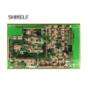
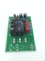
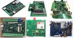
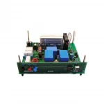
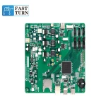
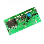
| Supplier Type | Bluetooth Circuit Board | Model Number | SH009 |
| Place of Origin | Guangdong, China | Product name | SHINELF Bluetooth Headset Circuit Board PCB |
| Product type | OEM Rigid PCB | Usage | PCB Manufactur And Assembly |
| Application | bluetooth pcb,audio pcb board | Material | FR4 94v0 Circuit Board |
| Color | Green Blue Black Red White And Other | Function | circuit board assembly |
| Layer | 4-22 layers | PCB test | High-stringency 100% Visual Inspection |
| PCB Assembly Method | Mixed SMD SMT DIP |


|
Feature
|
SHINELF
Multilayer PCBs Technical specification
|
|
Number of layers
|
4 – 22 layers standard, 30 layers advanced, 40 layers
prototype.
|
|
Technology highlights
|
Multiple layers of epoxy glass fiber bonded together
with multiple layers of copper of varying
thicknesses.
|
|
Materials
|
High performance FR4, halogen-free FR4, low loss and
low Dk materials
|
|
Copper weights (finished)
|
18μm – 210μm, advanced 1050μm / 30oz
|
|
Minimum track and gap
|
0.075mm / 0.075mm
|
|
PCB thickness
|
0.40mm – 7.0mm
|
|
Maxmimum dimensions
|
580mm x 1080mm, advanced 610mm x 1400mm
|
|
Surface finishes available
|
HASL (SnPb), LF HASL (SnNiCu), OSP, ENIG, Immersion
Tin, Immersion Silver, Electrolytic gold, Gold
fingers
|
|
Minimum mechanical drill
|
0.20mm
|
|
Feature
|
SHINELF HDI
PCBs Technical specification
|
|
Number of layers
|
4 – 22 layers standard, 30 layers advanced
|
|
Technology highlights
|
Multilayer boards with a higher connection pad
density than standard boards,
with finer lines/spaces, smaller via holes and
capture pads allowing microvias
to only penetrate select layers and also be placed
in surface pads.
|
|
HDI builds
|
1+N+1, 2+N+2, 3+N+3,4+N+4, any layer in R&D
|
|
Materials
|
FR4 standard, FR4 high performance, Halogen free FR4,
Rogers
|
|
Copper weights (finished)
|
18μm – 70μm
|
|
Minimum track and gap
|
0.075mm / 0.075mm
|
|
PCB thickness
|
0.40mm – 3.20mm
|
|
Maxmimum dimensions
|
610mm x 450mm; dependant upon laser drilling machine
|
|
Surface finishes available
|
OSP, ENIG, Immersion tin, Immersion silver,
Electrolytic gold, Gold fingers
|
|
Minimum mechanical drill
|
0.15mm
|
|
Minimum laser drill
|
0.10mm standard, 0.075mm advanced
|
|
Feature
|
SHINELF Radio
Frequency PCBs Technical specification
|
|
Number of layers
|
2-20 layers
|
|
Technology highlights
|
Controlled impedance, low loss materials,
miniaturization
|
|
Materials
|
Low loss / low Dk, higher performance FR-4, PPO,
Teflon, hydrocarbon / ceramic filled
|
|
Dielectric thickness
|
0.1mm – 3.0mm
|
|
Profile method
|
Routing, v-score
|
|
Copper weights (finished)
|
½ to 6 ounce
|
|
Minimum track and gaps
|
0.075mm / 0.075mm
|
|
Metal core thickness
|
0.4-2mm post bonded
|
|
Maxmimum dimensions
|
580mm x 1010mm
|
|
Surface finishes available
|
HASL (Lead-free), OSP, ENIG, Immersion tin, Immersion
silver
|
|
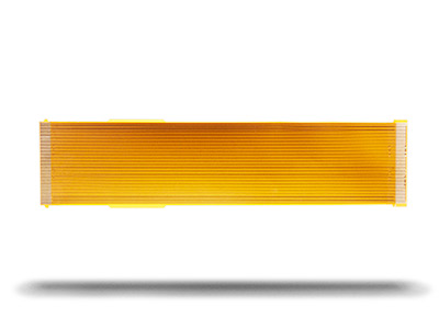
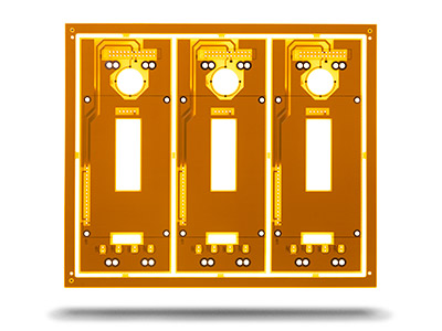
Feature
|
SHINELF Flexible
PCBs (Flex)
|
|
Number of layers
|
1 – 6L
|
|
Technology highlights
|
Mainly polyimide materials, flex PCB’s are necessary
when motion of the PCB is needed, when 3-D
interconnections are necessary(i.e. replacing cables
and connectors) or when these are both combined due
to limited available space.
|
|
Materials
|
Polyimide, Polyester
|
|
Profile method
|
Laser cutting, punching, rout
|
|
Copper weights (finished)
|
18μm – 70μm
|
|
Minimum track and gap
|
0.075mm / 0.075mm
|
|
PCB thickness
|
0.05mm – 0.80mm
|
|
Maxmimum dimensions
|
450mm x 610mm
|
|
Surface finishes available
|
OSP, ENIG, Immersion tin, Electrolytic gold, Gold
fingers
|
|
Minimum mechanical drill
|
0.15mm
|
|
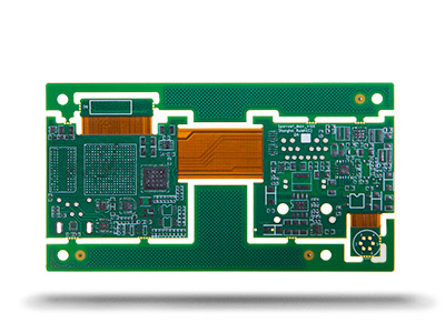
Feature
|
SHINELF Rigid-Flex PCBs – Technical
specification
|
|
Number of layers
|
4-16 layers
|
|
Technology highlights
|
Mixed materials including RF and high speed, standard
FR-4, polyimide flex.
Adhesiveless or adhesive based polyimide
flexconstructions, with cover coat
or flexible solder mask materials.
|
|
Bending performance
|
Based on the specific design, the bend performance
can range from a basic
90 °bend to fit to a full dynamic flex with 360°
rangeof motion in the flex tail
that will withstand continuous cycles throughout
the product life.
|
|
Bend features
|
Bend radius controls the flexibility of the flex
portion of the board. The thinner
the material the lower the bend radius and the more
flexible the flex section
|
|
Materials
|
RA copper, HTE copper, FR-4, polyimide, adhesive
|
|
Copper weights (finished)
|
½ ounce, 1 ounce, 2 ounce, 3 ounce
|
|
Minimum track and gap
|
0.075mm / 0.075mm
|
|
PCB thickness
|
0.4mm to 3mm
|
|
PCB thickness in flex section
|
0.05mm to 0.8mm
|
|
Maxmimum dimensions
|
457mm to 610mm
|
|
Surface finishes available
|
ENIG, OSP Immersion tin, Immersion silver
|
|
Minimum mechanical drill
|
0.20mm
|
|
Item
|
Processing Capacity
|
Process Details
|
|
Number of layers
|
2 layers
|
|
|
Ink
|
Sun series
|
White oil: Sun 2000 series, green oil: Sun 07 series
|
|
Plate type
|
FR-4 standard, FR-4 high performance, FR-4
halogen-free.
|
|
|
Dimensional accuracy
|
±0.15mm
|
CNC shape tolerance ±0.15mm, V-cut board shape
|
|
Thickness range
|
0.2-2.4mm
|
Current plate thickness:
0.4/0.6/0.8/1.0/1.2/1.6/2.0/2.4 mm
|
|
Thickness tolerance( t≥1.0mm)
|
± 10%
|
Please pay attention to this point: due to the
production process (sink copper, solder mask, pad
spraying will increase the thickness of the board),
generally go to the right tolerance
|
|
Thickness tolerance ( t
|
One moment please
 Member's Area
 Messages
  Need Help