Join World's Fastest Growing B2B Network
Join World's Fastest Growing B2B Network


| MOQ | 10 Piece |
| Port | Shanghai |
| Packaging | Export suitable package |
| Lead Time | 15~30 days |
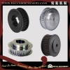
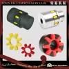
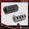
Friction torque limiter is a protective device that restricts torque transfer in the drive system by sliding when the torque needs exceed a preset value due to shock load, overload, overload, or machine jamming. The minimum to have low-cost protection. Torque Limiter is operated with a spring friction surface that adjusts the spring force to provide slip torque. Recca friction type torque limiter can be mounted on a shaft, capable of transmission with a sprocket, gear, pulley, roller chain, or flange as a centerpiece and sandwiched between two friction lining plates. It enables the safe operation of protective equipment at the lowest possible cost.
1. Determine the required slip torque from the loading
conditions or from the design strength of the machine. If
the loading conditions of the machine are unknown, set the
required slip torque of the Torque limiter to 1.5 to 2
times of the torque that the motor produces on the shaft
where the Torque limiter is mounted.
2. Select a Torque limiter which has enough torque range
and bore range.
3. Determine the proper bushing length from the thickness
of the center member to be inserted between the friction
facings. Always choose the largest bushing which does not
exceed the width of the center member. Maximum thickness of
the center member is shown as ’ S(max)’ in the dimension
table.
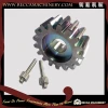
1. Process the friction face of center parts to ensure the
rated torque, planeness and parallelism in line with the
bore and protect the partsfrom the rust and oil. The
recommended surface roughness (Ra) is1.6. The sliding
torque will be not stable if the center part is
defected.
2. Please process the bore of center parts according to the
followingTable and, select sprocket with min. teeth number
and lining ringlength.
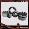
Tight and loose the adjusting bolts or nuts to set the torque of the Torque Limiter. The Limiter from size RTL50 to RTL89 depend upon theadjusting nuts, whereas RTL127 and RTL178 depends upon the adjusting bolts. Set the torque after mounting the Limiter upon the shaft as follow:
For sizes from RTL50 to RTL89
Rotate to tight the adjusting nuts by hands to fix thedisc
spring and plate. Then, try to tight the nuts (about 60C)
by wrench.
For sizes from RTL127 to RTL178
First, rotate the nuts to tight the disc spring and
pressure plate.Then tight all the adjusting bolts (about
60°)
If the Limiter slides with normal loading, please tight the
nuts (for sizes from RTL50 to RTL89) or bolts (from RTL127
to RTL178) generally until the Limiters stop sliding.
Please ensure that each bolt is tightened or lossened
averagely.
Find out the setting torque appropriate for the equipments
aftertests. Please refer the following Table that shows the
relationship between the effective rotation angle and
torque setting.
To make torque setting precisely, we recommend you to use
Torque Limiter for trial once. For example, while the
rotation speed is 50~60 rpm with 500 circles, rotate the
adjusting nuts or bolts around 45°.


Dimensions In mm
One moment please
 Member's Area
 Messages
  Need Help