Join World's Fastest Growing B2B Network
Join World's Fastest Growing B2B Network


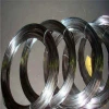
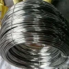
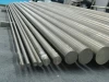
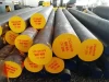
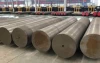
DOM Tubing (Drawn over Mandrel) is a cold drawn 1020 to 1026 or ST52.3 grade seamless steel tube to drawing to size. Cold drawing DOM to size allows for higher yield and tensile strengths. In comparison to other tubing, DOM is produced to more exact OD and ID tolerances. This allows for minimal machine time and has the highest strength possible.
l Stocked and produced various size range
l Cut to length service available
l Suitable to hone sizes
l Custom sizes available upon request
l All the common off road sizes available
l Uniform wall thickness with close OD and ID tolerances
l Uniform grain structure and controlled hardness
l High Yield and Tensile Strength
l Smooth and Clean OD and ID surfaces
l OD and ID concentric
l Excellent machining characteristics
l Hydraulic Cylinders
l Auto and Truck Axles
l Suspension parts and shock absorbers
l High Speed Shafts and rollers
l Bearings and Spacers
l Roll cages
l Agricultural components and many other machined tubular parts.
l Pre-honed tube
l EN10305 Steel Tubes for Precision Applications Seamless Cold Drawn Tubes
l DIN 2391 Seamless Precision Steel Tubes
l ASTM A519 Seamless Carbon and Alloy Steel Mechanical Tubing
|
Grade |
Chemistry |
% |
Yield |
Tensile |
Elongation |
Typical Hardness |
|
PSI |
PSI |
% in 2" section |
Min |
|||
|
1020 |
Carbon |
0.150 - 0.200 |
60000 |
70000 |
10 |
B-75 |
|
MN |
0.300 - 0.600 |
|||||
|
P |
0.035 Max |
|||||
|
S |
0.035 Max |
|||||
|
1026 |
Carbon |
0.220 - 0.280 |
70000 |
80000 |
10 |
B-80 |
|
MN |
0.600 - 0.900 |
|||||
|
P |
0.035 Max |
|||||
|
S |
0.035 Max |
|||||
|
ST52.3 |
Carbon |
0.140 - 0.180 |
75000 |
85000 |
15 |
B-80 |
|
Si |
0.150 - 0.300 |
|||||
|
MN |
1.200 - 1.400 |
|||||
|
P |
0.020 max |
|||||
|
S |
0.010 max |
|
OD Inches |
Wall: |
OD Inches |
ID Inches |
||
|
Size Range |
Percent of OD |
Plus |
Minus |
Plus |
Minus |
|
Up to 0.499 |
All |
0.004 |
0 |
||
|
0.500-1.699 |
All |
0.005 |
0 |
0 |
0.005 |
|
1.700-2.099 |
All |
0.006 |
0 |
0 |
0.006 |
|
2.100-2.499 |
All |
0.007 |
0 |
0 |
0.007 |
|
2.500-2.899 |
All |
0.008 |
0 |
0 |
0.008 |
|
2.900-3.299 |
All |
0.009 |
0 |
0 |
0.009 |
|
3.300-3.699 |
All |
0.01 |
0 |
0 |
0.01 |
|
3.700-4.099 |
All |
0.011 |
0 |
0 |
0.011 |
|
4.100-4.499 |
All |
0.012 |
0 |
0 |
0.012 |
|
4.500-4.899 |
All |
0.013 |
0 |
0 |
0.013 |
|
4.900-5.299 |
All |
0.014 |
0 |
0 |
0.014 |
|
5.300-5.549 |
All |
0.015 |
0 |
0 |
0.015 |
|
5.550-5.999 |
Under 6 |
0.01 |
0.01 |
0.01 |
0.01 |
|
6 and Over |
0.009 |
0.009 |
0.009 |
0.009 |
|
|
6.000-6.499 |
Under 6 |
0.013 |
0.013 |
0.013 |
0.013 |
|
6 and Over |
0.01 |
0.01 |
0.01 |
0.01 |
|
|
6.500-6.999 |
Under 6 |
0.015 |
0.015 |
0.015 |
0.015 |
|
6 and Over |
0.012 |
0.012 |
0.012 |
0.012 |
|
|
7.000-7.499 |
Under 6 |
0.018 |
0.018 |
0.018 |
0.018 |
|
6 and Over |
0.013 |
0.013 |
0.013 |
0.013 |
|
|
7.500-7.999 |
Under 6 |
0.02 |
0.02 |
0.02 |
0.02 |
|
6 and Over |
0.015 |
0.015 |
0.015 |
0.015 |
|
|
8.000-8.499 |
Under 6 |
0.023 |
0.023 |
0.023 |
0.023 |
|
6 and Over |
0.016 |
0.016 |
0.016 |
0.016 |
|
|
8.500-8.999 |
Under 6 |
0.025 |
0.025 |
0.025 |
0.025 |
|
6 and Over |
0.017 |
0.017 |
0.017 |
0.017 |
|
|
9.000-9.499 |
Under 6 |
0.028 |
0.028 |
0.028 |
0.028 |
|
6 and Over |
0.019 |
0.019 |
0.019 |
0.019 |
|
|
9.500-9.999 |
Under 6 |
0.03 |
0.03 |
0.03 |
0.03 |
|
6 and Over |
0.02 |
0.02 |
0.02 |
0.02 |
|
|
10.000-10.999 |
All |
0.034 |
0.034 |
0.034 |
0.034 |
|
11.000-11.999 |
All |
0.035 |
0.035 |
0.035 |
0.035 |
|
12.000-12.999 |
All |
0.036 |
0.036 |
0.036 |
0.036 |
|
13.000-13.999 |
All |
0.037 |
0.037 |
0.037 |
0.037 |
|
14.000-15.000 |
All |
0.038 |
0.038 |
0.038 |
0.038 |
|
Wall Thickness |
Including .375" to .875" OD |
Over .875" to 1.875" OD |
Over 1.875" to 3.750" OD |
Over 3.750 "to 15.000" OD |
||||
|
(Inches) |
Plus |
Minus |
Plus |
Minus |
Plus |
Minus |
Plus |
Minus |
|
0.035 |
0.002 |
0.002 |
0.002 |
0.002 |
0.002 |
0.002 |
||
|
0.049 |
0.002 |
0.002 |
0.002 |
0.003 |
0.002 |
0.003 |
||
|
0.065 |
0.002 |
0.002 |
0.002 |
0.003 |
0.003 |
0.003 |
0.004 |
0.004 |
|
0.083 |
0.002 |
0.002 |
0.002 |
0.003 |
0.003 |
0.003 |
0.004 |
0.005 |
|
0.095 |
0.002 |
0.002 |
0.002 |
0.003 |
0.003 |
0.003 |
0.004 |
0.005 |
|
0.109 |
0.002 |
0.003 |
0.002 |
0.004 |
0.003 |
0.003 |
0.005 |
0.005 |
|
0.12 |
0.003 |
0.003 |
0.002 |
0.004 |
0.003 |
0.003 |
0.005 |
0.005 |
|
0.134 |
0.002 |
0.004 |
0.003 |
0.003 |
0.005 |
0.005 |
||
|
0.148 |
0.002 |
0.004 |
0.003 |
0.003 |
0.005 |
0.005 |
||
|
0.165 |
0.003 |
0.004 |
0.003 |
0.004 |
0.005 |
0.006 |
||
|
0.18 |
0.004 |
0.004 |
0.003 |
0.005 |
0.006 |
0.006 |
||
|
0.203 |
0.004 |
0.005 |
0.004 |
0.005 |
0.006 |
0.007 |
||
|
0.22 |
0.004 |
0.006 |
0.004 |
0.006 |
0.007 |
0.007 |
||
|
0.238 |
0.005 |
0.006 |
0.005 |
0.006 |
0.007 |
0.007 |
||
|
0.259 |
0.005 |
0.006 |
0.005 |
0.006 |
0.007 |
0.007 |
||
|
0.284 |
0.005 |
0.006 |
0.005 |
0.006 |
0.007 |
0.007 |
||
|
0.3 |
0.006 |
0.006 |
0.006 |
0.006 |
0.008 |
0.008 |
||
|
0.32 |
0.007 |
0.007 |
0.007 |
0.007 |
0.008 |
0.008 |
||
|
0.344 |
0.008 |
0.008 |
0.008 |
0.008 |
0.009 |
0.009 |
||
|
0.375 |
0.009 |
0.009 |
0.009 |
0.009 |
||||
|
0.4 |
0.01 |
0.01 |
0.01 |
0.01 |
||||
|
0.438 |
0.011 |
0.011 |
0.011 |
0.011 |
||||
|
0.46 |
0.012 |
0.012 |
0.012 |
0.012 |
||||
|
0.48 |
0.012 |
0.012 |
0.012 |
0.012 |
||||
|
0.531 |
0.013 |
0.013 |
0.013 |
0.013 |
||||
|
0.563 |
0.013 |
0.013 |
0.013 |
0.013 |
||||
|
0.58 |
0.014 |
0.014 |
0.014 |
0.014 |
||||
|
0.6 |
0.015 |
0.015 |
0.015 |
0.015 |
||||
|
0.625 |
0.016 |
0.016 |
0.016 |
0.016 |
||||
|
0.65 |
0.017 |
0.017 |
0.017 |
0.017 |
||||
Ovality shall be within the above tolerances except when the wall thickness is less than 3% of the OD. In those cases the additional ovality shall be as follows, but the mean diameter shall be within the specified tolerance.
|
Outside Diameter |
Additional Ovality Tolerance (Inches) |
|
(Inches) |
|
|
Up to 2 |
0.01 |
|
Over 2 - 3 |
0.015 |
|
Over 3 - 4 |
0.02 |
|
Over 4 - 5 |
0.025 |
|
Over 5 - 6 |
0.03 |
|
Over 6 - 7 |
0.035 |
|
Over 7 - 8 |
0.04 |
|
Over 8 - 9 |
0.045 |
|
Over 9 - 10 |
0.05 |
|
Over 10 - 11 |
0.055 |
|
Over 11 - 12 |
0.06 |
|
Over 12 - 12.500 |
0.065 |
|
Outside Diameter |
Straightness Tolerance for any 3' of Length |
|
< 8.000" |
0.030" |
|
≥ 8.000" |
0.060" |
The following chart lists the nominal pressure ratings of tubing products which conform to SAE J524, SAE J525, SAE J526 and SAE J365.
|
Nominal Tube O.D. |
Nominal Tube Wall Thickness |
||||||||||||
|
0.028 |
0.035 |
0.049 |
0.065 |
0.083 |
0.093 |
0.109 |
0.120 |
0.134 |
0.148 |
0.156 |
0.188 |
||
|
inch |
mm |
0.71mm |
0.89mm |
1.24mm |
1.65mm |
2.11mm |
2.41mm |
2.77mm |
3.05mm |
3.40mm |
3.76mm |
3.96mm |
4.78mm |
|
Reference Working Pressures at 4:1 Design Factor(psi/MPa) |
|||||||||||||
|
0.125 |
6650 |
8450 |
|||||||||||
|
3.18 |
46.0 |
58.5 |
|||||||||||
|
0.188 |
4250 |
5450 |
|||||||||||
|
4.77 |
29.5 |
37.5 |
|||||||||||
|
0.250 |
3100 |
3950 |
5750 |
7800 |
|||||||||
|
6.35 |
21.5 |
27.0 |
39.5 |
54.0 |
|||||||||
|
0.312 |
2450 |
3100 |
4500 |
6150 |
|||||||||
|
7.92 |
16.8 |
21.5 |
31.0 |
42.5 |
|||||||||
|
0.375 |
2000 |
2550 |
3650 |
5000 |
6550 |
7600 |
|||||||
|
9.53 |
13.8 |
17.6 |
25.0 |
34.5 |
45.0 |
52.5 |
|||||||
|
0.500 |
1850 |
2700 |
3650 |
4800 |
5550 |
6450 |
7200 |
||||||
|
12.70 |
12.8 |
18.6 |
25.0 |
33.0 |
38.5 |
44.5 |
49.5 |
||||||
|
0.625 |
1500 |
2100 |
2850 |
3750 |
4350 |
5050 |
5600 |
||||||
|
15.88 |
10.4 |
14.5 |
19.6 |
26.0 |
30.0 |
35.0 |
38.5 |
||||||
|
0.750 |
1200 |
1750 |
2350 |
3050 |
3550 |
4150 |
4600 |
||||||
|
19.05 |
8.3 |
12.0 |
16.2 |
21.0 |
24.5 |
28.5 |
31.5 |
||||||
|
0.875 |
1050 |
1500 |
2000 |
2600 |
3000 |
3500 |
3900 |
||||||
|
22.23 |
7.2 |
10.4 |
13.8 |
18.0 |
20.5 |
24.0 |
27.0 |
||||||
|
1.000 |
900 |
1300 |
1750 |
2250 |
2600 |
3000 |
3350 |
3800 |
4200 |
||||
|
25.40 |
6.2 |
9.0 |
12.0 |
15.5 |
18.0 |
20.5 |
23.0 |
26.0 |
29.0 |
||||
|
1.125 |
1150 |
1550 |
2000 |
2300 |
2650 |
2950 |
3300 |
3700 |
|||||
|
28.58 |
7.9 |
10.6 |
13.8 |
15.8 |
18.2 |
20.5 |
23.0 |
25.5 |
|||||
|
1.250 |
1000 |
1350 |
1750 |
2050 |
2350 |
2650 |
2950 |
3300 |
3500 |
4300 |
|||
|
31.75 |
6.9 |
9.3 |
12.0 |
14.2 |
16.2 |
18.2 |
20.5 |
23.0 |
24.0 |
29.5 |
|||
|
1.500 |
1150 |
1450 |
1700 |
1950 |
2150 |
2450 |
2700 |
2850 |
3500 |
||||
|
38.10 |
7.9 |
10.0 |
11.8 |
13.5 |
14.8 |
16.8 |
18.6 |
19.6 |
24.0 |
||||
|
1.750 |
950 |
1250 |
1450 |
1650 |
1850 |
2050 |
2300 |
2400 |
2950 |
||||
|
44.45 |
6.6 |
8.6 |
10.0 |
11.4 |
12.8 |
14.2 |
15.8 |
16.6 |
20.5 |
||||
|
2.000 |
850 |
1100 |
1250 |
1450 |
1600 |
1800 |
2000 |
2100 |
2550 |
||||
|
50.80 |
5.9 |
7.6 |
8.6 |
10.0 |
11.0 |
12.4 |
13.8 |
14.5 |
17.6 |
||||
*Calculation of Design Pressures for Alternate Tubing Materials
*Design pressures for alternate tubing materials may be calculated using the Lame formula as follows: P=S((D2-d2)/(D2+d))where:
D= nominal outside diameter of tubing
d= nominal inside diameter of tubing
P= design pressure
S= allowable fiber stress of material at 4:1 design factor
Fushun Metal is a large special steel manufacturer and supplier. We are metal experts and have been providing quality customer service and products since 1998.
At Fushun Metal, we supply a wide range of metals for a variety of applications. Our products/stock includes: cold rolled steel tube, cold drawn steel tube, hollow bar, boiler tube, alloy steel tube, stainless steel tube, nickel alloy pipe,etc
We also can supply move services like heat-treatment(QT, +A, +N, +SR, +BKS), grounded, polished, cutting, beveled, painted, threaded, upsetting, boring, honing etc.
Send your inquiry information to us and get a free quotation today!
One moment please
 Member's Area
 Messages
  Need Help