Join World's Fastest Growing B2B Network
Join World's Fastest Growing B2B Network


| MOQ | 1 Piece/Pieces |
Product
function improvements:
Reduced
the oscilloscope's own noise.
Added
waveform save function, the waveform is not
lost after shutdown.
The
function of detecting short circuit and open
circuit is added, which can help the
assembler to find welding errors and improve
the assembly success rate.
Added TFT
controller identification function
2.4
inch TFT color
screen
STM microcontroller
Electronic kit customized for
students
Latest
improvements!
DSO138 oscilloscope can already directly
display various parameters of the waveform,
including frequency, period, pulse
width, duty cycle, maximum value, minimum
value, average value, peak-to-peak value and
effective value, which is of great
help to intuitively understand the waveform
characteristics. And the effective value
displayed is the true effective value, not
affected by the shape of the
waveform.
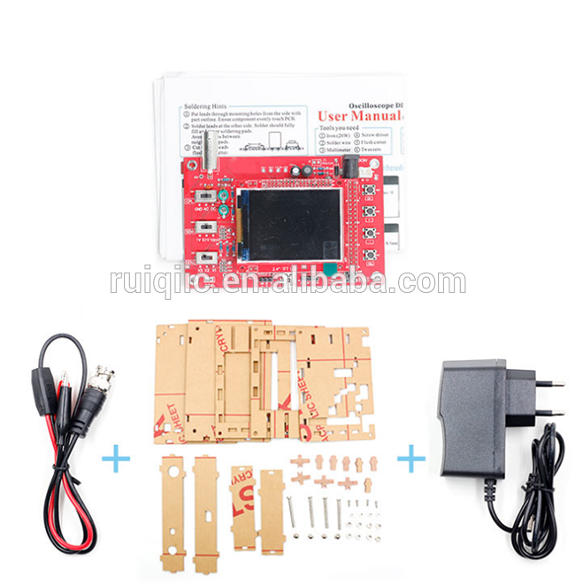
DSO138 oscilloscope production kit features:
Facing
electronic production training, the
explanation materials are complete and
detailed, including circuit diagrams,
production instructions, instructions for
use, troubleshooting methods, etc., and the
production success rate is high.
The variety of
components is suitable for students to
conduct component recognition, in-line
component welding, and patch component
welding training.
Students can
obtain a practical tool at the same time of
production, which can effectively observe and
measure the signal waveforms of audio, video
synchronization, low-frequency switching
power supply, infrared receiving and
transmitting and many other occasions to
increase learning interest and improve
learning effect.
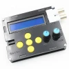
The kit uses
the ARM Cortex-M3 processor (STM32F103C8) and
contains a 2.4-inch color TFT display, which
can be used as an ARM development test
board.
The circuit is
simple and reliable, and the price is
low
DSO138 characteristic index:
Maximum
real-time sampling rate: 1Msps
Accuracy: 12Bit
Sampling buffer depth: 1024 bytes
Analog band width: 0-200KHz
Vertical sensitivity: 10mV / Div – 5V / Div
(Progress according to 1-2-5)
The vertical displacement can be adjusted
with instructions
Input impedance: 1MΩ
Maximum input voltage: 50Vpp (1: 1 probe),
400Vpp (10: 1 probe)
Coupling methods include DC / AC / GND
Horizontal time base range: 10μs / Div – 50s
/ Div (Progress according to 1-2-5)
With automatic, conventional and single
trigger mode, it is convenient to capture
instant waveform
Trigger on rising or falling edges
Trigger level position is adjustable with
indication
Observable waveform before trigger (negative
delay)
Waveform display can be frozen at any time
(HOLD function)
Comes with 1KHz /3.3V square wave test signal
source
With waveform parameter digital display, the
parameters that can be displayed are:
frequency, period, pulse width, duty cycle,
maximum, minimum, average, peak-to-peak
value, effective value
Save / recall the waveform, the shutdown
waveform does not disappear
To turn on / off the
display of waveform parameters:
place the cursor in the time base position
and long press the [OK] key.
Method of
saving waveform:
press [SEL] and [+] keys at the same
time.
To recall the saved waveform: press the [SEL]
and [-] keys at the same time.
To enter the
test mode:
hold down [OK] and then press the [RESET]
key, if you see the LED flashes quickly, it
means that there is a short circuit in the PB
or PC port of the microcontroller (these
ports include the connection to the LCD)
Remove after exiting; if you see the LED
flashing with a period of about 4 seconds,
you can use the voltmeter to find the
possible open circuit in the connection line
related to the microcontroller port
DSO150 characteristic index:
Maximum
real-time sampling rate: 1Msps
Accuracy:
12Bit
Sampling
buffer depth: 1024 bytes
Analog
band width: 0-200KHz
Vertical
sensitivity: 5mV / Div – 20V / Div (Progress
according to 1-2-5)
The
vertical displacement can be adjusted with
instructions
Input
impedance: 1MΩ
Maximum
input voltage: 50Vpp (1: 1 probe), 400Vpp
(10: 1 probe)
Coupling
methods include DC / AC / GND
Horizontal
time base range: 10μs / Div – 50s / Div
(Progress according to 1-2-5)
With
automatic, conventional and single trigger
mode, it is convenient to capture instant
waveform
Trigger on
rising or falling edges
Trigger
level position is adjustable with
indication
Observable
waveform before trigger (negative
delay)
Waveform
display can be frozen at any time (HOLD
function)
Comes with
1KHz /3.3V square wave test signal
source
With
waveform parameter digital display, the
parameters that can be displayed are:
frequency, period, pulse width, duty cycle,
maximum, minimum, average, peak-to-peak
value, effective value
Save /
recall the waveform, the shutdown waveform
does not disappear
Finished standard module + Test clip


Contact Person: Justin CAI
Company Address: NO. B2713,Oriental times square,Huaqiang notrh Road ,Futian District, Shenzhen, Guandong,China.
One moment please
 Member's Area
 Messages
  Need Help