Join World's Fastest Growing B2B Network
Join World's Fastest Growing B2B Network


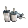
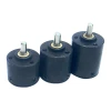
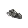
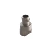
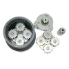
Product Photo:

Product parameter
:
| Parameter | symbol | conditions | value |
unit |
| Collector-Emitter Voltage | VCES | VGE=0V, IC =1mA, Tvj=25ºC | 1200 | V |
| Continuous Collector Current | IC | Tc=80ºC, Tvjmax=175ºC | 200 | A |
| Peak Collector Current | ICRM | tp=1ms | 400 | A |
| Gate-Emitter Voltage | VGES | Tvj=25ºC | ±20 | V |
| Total Power Dissipation (IGBT-inverter) | Ptot |
Tc=25ºC Tvjmax=175ºC |
1358 | W |
Features
Benefits
E63
IGBT module is one of the most popular
IGBT packages worldwide and is used in many different
applications, such as General Purpose Drives; Commercial,
Construction and Agricultural Vehicles as well as eBus; Solar;
Wind; Traction; UPS and finally, Transmission and Distribution.
In the latest module generation it is now feasible to increase
the module current to 75 A. This is possible through the new
IGBT7 technology enabling a higher power density and reduced BoM
costs.
Circuit
Diagram

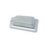
Package drawing

E53 Series
products:
| Model | Vces(V) | Ic(T=80)(A) | VCE(sat) Tj=125ºC | Eon+Eof(Tj=125)(mj) | Rthjc(KW) |
| WGL200B60F45 | 600 | 200 | 1.45 | 11.02 | 0.21 |
| WGL300B60F45 | 600 | 300 | 1.45 | 15.01 | 0.15 |
| WGL400B60F45 | 600 | 400 | 1.45 | 17.96 | 0.11 |
| WGL600B60F45 | 600 | 600 | 1.45 | 33.25 | 0.09 |
| WGF200B60F45 | 600 | 200 | 2.8 | 13.49 | 0.11 |
| WGF300B60F45 | 600 | 300 | 2.8 | 21.38 | 0.10 |
| WGF400B60F45 | 600 | 400 | 2.8 | 28.5 | 0.08 |
| WGL200B65F45 | 650 | 200 | 1.45 | 12.02 | 0.21 |
| WGL300B65F45 | 650 | 300 | 1.45 | 16.01 | 0.15 |
| WGL400B65F45 | 650 | 400 | 1.45 | 19.23 | 0.11 |
| WGL600B65F45 | 650 | 600 | 1.45 | 36.35 | 0.09 |
| WGL100B120F45 | 1200 | 100 | 1.9 | 17.48 | 0.14 |
| WGL150B120F45 | 1200 | 150 | 1.9 | 34.20 | 0.11 |
| WGL200B120F45 | 1200 | 200 | 1.9 | 37.05 | 0.10 |
| WGL300B120F45 | 1200 | 300 | 1.9 | 60.60 | 0.08 |
| WGL400B120F45 | 1200 | 400 | 1.9 | 80.75 | 0.05 |
| WGL450B120F45 | 1200 | 450 | 1.9 | 90.10 | 0.04 |
FAQ:
The
CETC
IGBT is developed to operate at a
continuous temperature of 175°C. The overload limitation is given
by the package. Most of the applications are designed with an
overload profile and here the IGBT is the perfect fit.
The
CETC
IGBT provides the lowest static
losses.
2.How to handle the high gate charge
specified for IGBT
datasheet?
The specified gate charge in the
datasheet is for an operation with VGE of
±
20
V. Most customers use VGE in the range
of
+5.4
V to
+7
V. Here the gate charge is much lower
and with this value, typical switching frequencies can be
addressed with standard
drives.
3.Technical
Support
In order to enable us to process your
inquiry as efficiently as possible and ensure your case is duly
reported, we kindly ask you to submit your request
via
our service
team.
One moment please
 Member's Area
 Messages
  Need Help